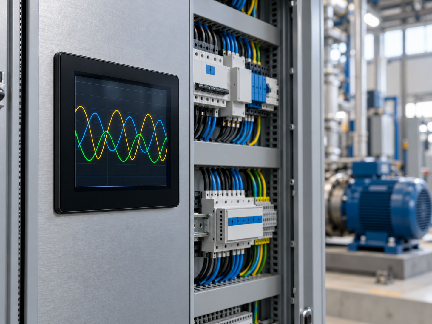
A measuring instrument may be precise, correctly sized, and perfectly suited to the application, yet still yield unreliable readings if installed incorrectly. Indeed, in electrical and industrial systems, the quality of the measurement depends not only on the instrument’s characteristics but also on the entire system in which it is integrated: connections, wiring, instrument transformers, power supply, electromagnetic interference, and configuration are all factors that can influence the result.
Errors in the installation of measuring instruments do not necessarily result in an obvious failure. In many cases, the device continues to operate and display seemingly plausible data, making it more difficult to identify the problem. A reading skewed by a few percentage points, an unstable signal, or a value that changes under specific operating conditions can thus be misinterpreted as genuine system phenomena.
Being aware of the most common errors makes it possible to prevent them during the design and wiring of the measurement system.
1. Choosing an instrument unsuited to the magnitude to be measured
The first error can occur even before the actual installation. An instrument must be selected by considering the electrical quantity involved, the expected measurement range, the type of signal available, and the characteristics of the system.
Installing an instrument with an unsuitable measurement range can significantly reduce the quality of the information obtained. For instance, a range that is excessively wide relative to the values normally present in the system can render the use of the available resolution less effective; conversely, values exceeding the intended range can lead to saturation, out-of-scale readings, or incorrect operating conditions.
The same principle applies to the input type. Voltage signals, direct current, process signals such as 0–20 mA or 4–20 mA, outputs from instrument transformers, and other quantities require compatible inputs and configurations.
Proper installation therefore begins with verifying the instrument’s technical specifications and their correspondence with the actual characteristics of the circuit.
2. Failure to follow the connection diagram
One of the seemingly simplest errors is also one of the most insidious: connecting the instrument without carefully following the manufacturer’s diagram.
The presence of seemingly similar terminals does not mean they can be used interchangeably. Auxiliary power supply, measurement inputs, analog outputs, contacts, digital communications, and connections to any transformers must be correctly distinguished.
Reversing the connections can result in values with the wrong sign, inconsistent readings, or a failure of the measurement function. In other cases, it may expose the instrument’s inputs to electrical conditions for which they were not designed.
Before commissioning, it is therefore advisable to verify the correspondence between the system’s electrical schematic, the instrument’s terminal block, and the technical documentation. This verification is particularly important for complex panels, where numerous conductors may be concentrated in confined spaces.
3. Making errors when connecting current transformers
When current is not measured directly but via a current transformer—commonly referred to as a CT—the installation of the transformer becomes an integral part of the measurement chain.
The transformation ratio, connection polarity, and the link between the secondary winding and the instrument must align with the design specifications. An incorrectly configured ratio can produce values that appear perfectly stable but do not represent the actual current flowing in the circuit.
The orientation of the transformer can also be of particular importance in applications where flow direction, power, and energy are considered. An installation with inconsistent polarity can affect the sign or the calculation of derived quantities.
Another fundamental aspect concerns the secondary circuit of the current transformer. The manufacturer’s instructions and the safety procedures applicable to the device in use must be strictly observed, avoiding any unauthorized interventions or configurations while the system is in operation.
4. Neglecting cable cross-section, length, and routing
Cabling is not merely a means of transmitting the signal from the instrument to the measurement point. It is part of the system and, in some applications, can directly influence the result.
Conductor length, section, overall resistance and electrical characteristics of the connection must be considered depending on the type of signal used. Particular attention is required when working with low level signals or when the sensor and instrument are installed at a considerable distance.
Cable routing is also important. Running signal conductors alongside power lines, motor supply lines, inverters, or other circuits involving high-frequency switching can increase the likelihood of electrical interference coupling into the measurement signals.
The result may manifest as unstable values, oscillations, spikes, or variations that do not correspond to the actual behavior of the monitored quantity.
5. Ignoring electromagnetic interference
Industrial environments can be characterized by the presence of numerous sources of electromagnetic interference. Motors, frequency converters, contactors, switching power supplies, power systems, and high-current cabling can generate disturbances capable of interfering with sensitive electronic circuits.
Electromagnetic compatibility therefore does not depend solely on the characteristics of the individual device; the way equipment and cabling are installed also contributes to the overall behavior of the system.
The separation of power and signal cables, proper shielding management, equipotential bonding, grounding, and component layout must be evaluated based on the specific system and applicable technical guidelines.
A common mistake is to attribute the cause of an unstable measurement solely to the instrument itself. Before replacing the device, it is useful to check whether the anomalies change—for instance, when a motor starts, an inverter activates, or other system operating conditions occur. The timing relationship between the disturbance and the measurement behavior can provide valuable clues during diagnosis.
6. Improperly handling shielding and grounding
Shielding and grounding are often considered secondary elements of cabling, but in electronic installations and measurement systems, they can play a decisive role in signal quality and overall safety.
Shielding installed without adhering to the system’s specified guidelines may fail to perform its function correctly. Similarly, grounding connections made without considering the system architecture can give rise to potential differences or create unwanted current paths.
There is no universal rule applicable indiscriminately to every instrument and system. The correct method depends on the signal type, the equipment used, the electromagnetic environment, and the manufacturer’s specifications.
For this reason, it is preferable to avoid solutions based solely on habit and to always check the technical documentation for the installed devices.
7. Configure parameters that differ from the system’s actual settings.
Modern digital instruments and analyzers often allow for the configuration of numerous parameters. This flexibility enables a device to be adapted to different applications, but it also introduces a potential source of error.
An incorrect transformation ratio, an incorrect scale, an input type different from the one actually connected, or inconsistently set network parameters can alter the displayed information without necessarily triggering an error message.
This is one of the most critical aspects, as the data can appear technically plausible. If, for instance, the instrument correctly receives the signal but applies a transformation ratio different from that of the installed transformer, the reading may be stable and repeatable yet numerically incorrect.
After installation, it is therefore useful to compare the configuration stored in the instrument with the design data and the specifications of the components actually present in the panel.
8. Failure to consider environmental conditions
Temperature, humidity, dust, vibration, ventilation, and the characteristics of the enclosure in which the instrument is installed can affect long-term reliability.
A panel-mounted instrument must be used under the conditions specified in the relevant technical documentation. Installing it near components that generate significant heat, or in a cabinet with insufficient ventilation, may create operating conditions different from those considered during the design phase.
The physical layout also warrants attention. In particularly compact panels, one should not merely consider whether all the available components will fit; it is also necessary to take into account terminal accessibility, heat dissipation, cable routing, and the feasibility of inspections and maintenance.
9. Neglecting nutrition and protective gear
Many electronic instruments require an auxiliary power supply. Using values incompatible with specifications, ignoring polarity indications, or underestimating the quality of the power supply can compromise the device’s operation.
In complex industrial networks, transient overvoltages and other electrical phenomena may also occur; these must be taken into account during system design and the selection of appropriate protective devices.
Indeed, the safety of measuring instruments cannot be separated from that of the circuit into which they are installed. Insulation, protection, measurement category (where applicable), and ratings must be compatible with the intended operating conditions.
Installing an instrument based solely on the quantity it is intended to display, without considering the electrical environment in which it will operate, means analyzing only part of the problem.
10. Skip the post-installation check
Finishing the wiring and verifying that the display turns on does not mean the measurement system is complete.
The commissioning phase should include a check of the consistency of the readings. The observed values must be consistent with what is expected from the system and, where possible, may be compared with known quantities or suitable reference instruments.
Values that are apparently anomalous but not clearly impossible deserve special attention. A complete absence of voltage where it ought to be present immediately prompts a search for a problem; a moderate deviation, on the other hand, can go unnoticed and persist in the system for a long time.
It is also useful to verify the measurement behavior under different operating conditions. An accurate reading taken while the plant is idle or under reduced load does not necessarily guarantee that the system will maintain the same behavior when high-power equipment starts operating or electrical conditions change.
An incorrect piece of data can seem perfectly credible.
The most insidious aspect of installation errors is precisely this: an instrument can appear to be working well while providing inaccurate measurements.
An incorrect connection, a wrongly configured transformation ratio, signal interference, or a wiring issue does not always produce obviously absurd values. They can generate mutually consistent figures that appear regularly and are thus easily mistaken for reliable data.
This becomes particularly important when the data is used by supervision, automation, or energy monitoring systems. In these applications, the value does not simply remain on the instrument’s display: it can be recorded, compared over time, used to calculate consumption, or transferred to other control systems.
An initial error in the measurement chain can therefore propagate to all subsequent processing stages.
How to reduce errors during the installation of measuring instruments
A successful installation begins with an analysis of the entire measurement chain. It is not enough to select a device with an appropriate accuracy class if the signal reaches the instrument via incorrect connections or is interpreted using the wrong parameters.
Before commissioning, it is advisable to verify the instrument’s compatibility with the quantity to be measured, the wiring diagram, any transformer ratios, the configuration, the power supply, the cable routing, and the environmental conditions. A final check of the readings completes this verification and allows for the detection of any anomalies before the data is used in business processes.
FC Misure develops and manufactures electronic instruments for measuring electrical quantities—including current and voltage transformers, shunts, transducers, panel meters, and power network analyzers—designed for industrial applications. Selecting the right device and correctly integrating it into the system are closely linked aspects; both contribute to the availability of reliable data for control and monitoring purposes.
Measurement accuracy begins with installation.
An instrument’s stated accuracy is a fundamental characteristic, but it must be considered within the context of a correctly designed and installed system. Cabling, instrument transformers, configuration, interference, power supply, and environmental conditions can all affect the quality of the final result.
For this reason, when a measurement appears inconsistent or unstable, one should not automatically assume the instrument is the sole possible cause. Analyzing the entire measurement chain often makes it possible to identify problems that might otherwise remain hidden.
Paying attention to installation therefore means not only reducing the risk of failure but, above all, ensuring that the data obtained truly represents the quantity one wishes to measure. In an industrial measurement system, the reliability of decisions depends, in fact, primarily on the reliability of the information collected.