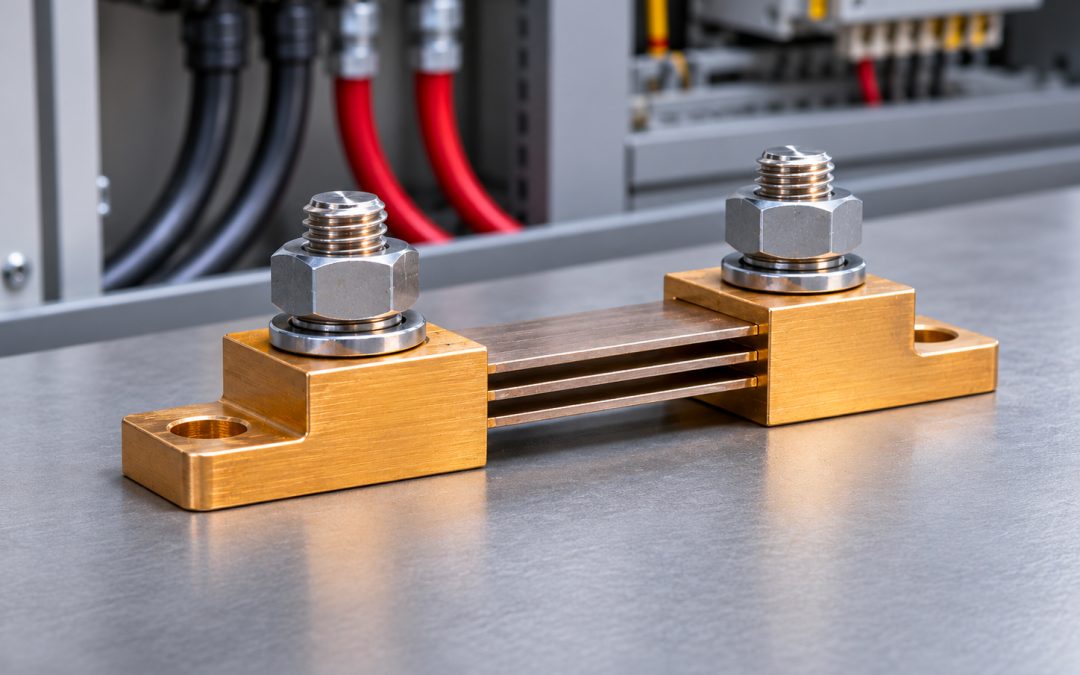
Measuring a high direct current is not as simple as connecting an ammeter to a circuit. In industrial plants, where hundreds or thousands of amperes can flow, measurement systems must provide reliable values without introducing excessive losses or impairing the operation of the installation.
Precision shunts, also called current dividers, address exactly this need. They are apparently simple components, but their correct sizing is essential to obtain reliable direct current (DC) measurements.
Let us look at how they work, which characteristics to consider when choosing one, and why aspects such as voltage drop, temperature and the quality of connections can significantly affect the measurement result.
What is a precision shunt and what is it used for?
A precision shunt is an electrical resistance of very low value, designed to be crossed by the current to be measured. Its task is to generate a small voltage drop, proportional to the current itself, which can be read by an ammeter, a digital instrument or an electronic acquisition system.
In practice, the shunt makes it possible to convert a quantity that is difficult to measure directly, such as a current of several hundred amperes, into a voltage signal of a few millivolts.
The principle is that of Ohm’s law:
V = R × I
where V is the voltage measured across the shunt, R the value of its resistance and I the current flowing through it.
Since the resistance is known, by measuring the voltage the current can be derived through the inverse relationship:
I = V / R
The resistance value is chosen so as to produce a voltage drop small enough not to significantly alter the circuit, yet high enough to be detected with the required accuracy.
This characteristic makes shunts particularly useful in DC distribution systems, industrial switchboards, power conversion plants and control equipment.
How a shunt works for DC current measurement
To understand how it works, it is worth starting from a concrete example.
Suppose we need to measure a direct current of 500 A and use a shunt with a rated voltage drop of 60 mV at maximum current.
Applying Ohm’s law, the rated resistance of the component is:
R = 0.060 V / 500 A = 0.00012 Ω
This is therefore a resistance of just 0.12 milliohm.
When 500 A flow through the shunt, the instrument connected to the measuring terminals detects 60 mV. If the current drops to 250 A, the rated voltage drop becomes 30 mV. At 100 A, on the other hand, it corresponds to 12 mV.
The relationship between current and voltage remains substantially linear within the intended operating range, taking into account the tolerance and thermal variations of the component.
This means that a suitably configured instrument can display the current value directly, without the operator having to perform the calculation every time.
Why are 60, 100 or 150 mV signals used?
Industrial shunts are available with different rated voltage drops. Values in use include 60, 100, 150 and 300 mV, although other configurations exist depending on the manufacturer and the application.
The choice is not neutral. A higher voltage drop generates a signal that is easier to distinguish from noise and stray voltages, but it also entails greater power dissipation for the same current.
Conversely, a shunt with a low voltage drop limits energy losses but requires an acquisition system capable of correctly measuring very small signals.
The best solution therefore arises from a trade-off between accuracy, dissipation, instrument characteristics and installation conditions.
What does the measurement accuracy of a shunt depend on?
Choosing a shunt with the correct rated current value is not enough to automatically obtain an accurate measurement. Performance depends on several factors, some related to the construction of the component, others to the operating conditions.
Accuracy class and tolerance
The accuracy class indicates the expected error limit according to the reference conditions and the specifications applicable to the device.
For example, for a class 0.5 shunt, the error limit conventionally referred to the rated value is 0.5%, according to the conditions stated by the manufacturer.
On a 500 A range, 0.5% of full scale equals 2.5 A. This value must not be confused with an error of 0.5% of the current actually measured at any point of the scale.
This is an important distinction, especially when the plant frequently operates at currents far below the rated one.
The error of the connected instrument, the resolution of the reading system and any drift introduced by temperature must also be considered.
Thermal stability and resistive materials
One of the main problems in measuring current through a resistance is the variation of the resistance value with temperature.
When a current flows through the shunt, part of the electrical energy is converted into heat. If the resistive material changed its characteristics significantly as the temperature varied, the measurement would be affected as well.
To limit this phenomenon, alloys with controlled temperature coefficients are used, including manganin, a material particularly suited to the construction of measuring resistors.
Manganin makes it possible to obtain stable resistance values within the intended operating range, helping to reduce errors caused by heating.
This does not mean that temperature can be neglected. In the presence of high currents, heat dissipation and environmental conditions remain essential factors to be assessed.
Quality of the electrical connections
Another often underestimated aspect concerns the connections.
When working with resistances in the order of milliohms or microhms, even a small additional resistance can become significant.
Loose terminals, oxidised surfaces and incorrectly sized connections can cause localised heating, unwanted voltage losses and, in certain configurations, measurement errors.
For this reason it is essential to follow the manufacturer’s installation instructions, keep contact surfaces clean and check that connections are properly tightened.
Four-terminal Kelvin connection: why it matters
Precision measurement systems often adopt the four-terminal connection, also known as the Kelvin connection.
The configuration distinguishes the connections that carry the main current from those used to detect the voltage drop.
The former are sized to carry the plant current. The latter are connected to the instrument and carry a negligible current, thanks to the high input impedance of the measurement system.
This separation makes it possible to limit the influence of the voltage drops present in the power conductors and in the related connections.
The advantage becomes particularly evident in high-current applications, where a few microhms of additional resistance can introduce non-negligible deviations.
A correct Kelvin connection therefore allows the voltage to be measured at the dedicated terminals of the shunt, avoiding the inclusion of most of the parasitic resistances of the external circuit in the reading.
Naturally, even in this case the manufacturer’s prescriptions must be respected: incorrect wiring can compromise the measurement or damage the connected electronics.
How to choose a precision shunt for an industrial plant
The selection of a shunt should start from the actual operating conditions and not only from the theoretical maximum current.
The first parameter to define is the rated current. The shunt must withstand the current expected under normal operating conditions, also considering any overloads and transients allowed by the specifications.
The second element is the rated voltage drop, which must be compatible with the input of the measuring instrument. An instrument configured for 60 mV at full scale, for example, cannot be matched indiscriminately with a 150 mV shunt without adequate reconfiguration or signal conversion.
The accuracy class required by the application must then be verified. A system intended for a general indication of current may have different requirements from a test bench or a particularly sensitive control application.
Finally, physical characteristics must be considered: dimensions, terminal arrangement, ventilation, ambient temperature and the possibility of integrating the component into the switchboard or equipment.
Power dissipation: a calculation not to be overlooked
Every shunt dissipates energy in the form of heat. The dissipated power can be calculated with the formula:
P = I × V
Let us return to the 500 A and 60 mV shunt used in the previous example.
At rated current, the dissipated power is:
P = 500 A × 0.060 V = 30 W
Thirty watts concentrated in a resistive component represent a thermal load that must be managed correctly.
If, while maintaining the same rated current, a 150 mV shunt were chosen, the dissipation would rise to 75 W.
This is why the choice of voltage drop affects not only the quality of the signal, but also the thermal management and energy losses of the plant.
For very high currents, multiple resistive elements, suitable mechanical structures and installation conditions that favour heat dissipation may be required.
Shunts and current transformers: what are the differences?
Shunts are sometimes compared with current transformers, but the two devices are not interchangeable in every application.
The traditional current transformer, commonly referred to as a CT, uses the principle of electromagnetic induction to obtain a secondary current proportional to the primary one. Precisely because of its operating principle, it is not suitable for measuring a steady direct current.
The shunt, by contrast, relies on an electrical resistance and can therefore be used directly in direct current circuits.
A further difference concerns galvanic isolation. The traditional CT allows the measuring circuit to be electrically separated from the primary circuit, whereas a passive shunt does not offer this separation.
If the application requires isolation, isolated acquisition electronics must be provided, or DC current sensors based on other technologies, such as Hall effect sensors, must be considered.
The choice therefore depends on the type of current, the required level of isolation, the desired accuracy and the operating conditions.
Where are DC current shunts used?
The industrial applications of shunts are numerous and concern all those systems in which it is necessary to know precisely the current flowing through a DC circuit.
Photovoltaic plants and storage systems
In photovoltaic systems and energy storage plants, measuring direct current is useful for monitoring energy flows and verifying the behaviour of the equipment.
A suitably sized shunt can be integrated into supervision systems to detect the current in specific branches of the circuit, through an appropriate measurement interface.
Railway sector and marine applications
Railway and marine electrical systems may include direct current circuits characterised by significant loads and demanding operating conditions.
In these contexts, in addition to accuracy, mechanical robustness, stability over time and the suitability of the component for the installation environment become particularly relevant.
Industrial automation and test benches
In automation systems, the shunt can contribute to monitoring the current draw of motors, power supplies, converters and other equipment supplied with direct current.
On test benches, on the other hand, accurate current measurement is often necessary to verify the performance of a device, analyse its behaviour under load or compare results obtained under different operating conditions.
In these cases the accuracy of the overall system, and not only of the individual shunt, becomes an essential parameter.
The most common installation and measurement errors
A correctly sized shunt can still provide unreliable readings if it is not installed and used in the appropriate way.
A first error consists in matching components and instruments with non-corresponding full scales. If the ratio between rated current and rated voltage is not configured correctly, the displayed value will be wrong even when the component works perfectly.
Another critical issue is installation in poorly ventilated spaces, especially when the shunt operates at high currents for prolonged periods.
Heating can alter the measurement conditions and, in the most severe cases, take the component beyond its intended operating limits.
Attention must then be paid to the routing of the signal conductors, which can be exposed to electrical noise from converters, drives and nearby power circuits.
For particularly sensitive applications it may be appropriate to use differential connections, shielding and acquisition systems suited to the electromagnetic conditions of the plant.
Finally, the rated accuracy of the shunt must not be confused with that of the entire measurement chain: every element, from the reading instrument to the wiring, can contribute to the overall uncertainty.
Standard shunts and shunts with integrated transducer
A traditional shunt produces a millivolt signal that must be interpreted by a compatible instrument.
In some industrial applications it may be more practical to use a solution with an integrated transducer, capable of converting the detected voltage into a standard signal, for example 4–20 mA or 0–10 V.
This configuration can simplify connection to PLCs, SCADA systems and supervision equipment, especially when the measuring point is far from the central control system.
The choice between the two solutions depends on the plant architecture, the transmission distances, the need for galvanic isolation and the characteristics of the available inputs.
The most complex device is not always the most suitable: when a local instrument compatible with the millivolt output is available, a passive shunt can be a simple and effective solution.
When should a shunt be calibrated?
The stability of a shunt does not remove the need to periodically check the reliability of the measurement, especially in applications where small deviations can affect the result of a test or a process.
The frequency of the checks depends on the operating conditions, the criticality of the measurement, the manufacturer’s instructions and the metrological requirements of the application.
The check may involve comparison with a suitable reference system, verifying the relationship between the applied current and the detected voltage drop.
If anomalous results occur, it is advisable to also examine the condition of the connections, thermal effects and the operation of the acquisition instrument before attributing the error solely to the shunt.
FC Misure’s solutions for DC current measurement
Choosing the most suitable shunt requires an assessment that brings together electrical characteristics, accuracy, environmental conditions and integration methods.
FC Misure offers a range of precision shunts and dividers for direct current, with solutions for industrial, railway, marine, photovoltaic and telecommunications applications.
The range includes configurations with different rated currents and voltage drops, as well as the possibility of evaluating customised versions according to the project specifications.
For plants that require particular characteristics, such as specific dimensions, dedicated terminals or signal interfaces, it is useful to define the operating conditions and the expected performance from the outset.
A correctly selected and installed precision shunt is a fundamental element for obtaining reliable direct current measurements. Its effectiveness, however, depends on the entire system into which it is integrated.
Do you need to choose a shunt for a new application or replace an existing component? Explore the solutions available on the FC Misure website and request a technical consultation to identify the configuration best suited to the requirements of your plant.